2004-2009
Mazda3/MAZDASPEED3
Fog Light switch modification how-to
by Edwin Man
Copyright © 2005-2008 Edwin Man. All rights
reserved. No
reproduction by any means permitted.
The following instructions will allow the stock fog lights to
function while only the parking lights are on as well as when the high
beams are on.
This allows for increased user control over the fog lights and allow
them to be used as independantly during extremely foggy conditions
where the use of headlights cause excessive backglare. It will also
allow maximum lighting output when you are on a dark road where you
want as much light on the road as possible.
These instructions are intended for North American models only since
Mazda3's in other continents do not require this modification (the fog
lights work with just the parking lights on). These instructions work
with all North American models (US/Canada/Mexico) with both halogen and
HID headlight systems. For Canadian models, Daytime Running Light (DRL)
functionality is still retained and illegally disabling that system is
beyond the scope of this how-to.
Since you will be messing with important (lighting) safety equipment on
your car, a solder splice method in this how-to will be used. Crimp on
"butt" connectors are NOT recommended.
Required time: 1 hour
Difficulty level: Moderately Difficult
Required tools:
- 10mm wrench
- 1 40lbs tensile strength black zip tie
- 40 watt soldering iron
- solder
- wire stripper
- wire cutter
- 1/8" heat shrink tubing
- heat gun, cigarette lighter, or matches
- good quality commerical grade black electrical tape (ie: 3M
Super 33+)
- pocket knife or razor blade
Basic disclaimer: work carefully and take your time.
If you screw
up, it's your fault. Always excercise caution when working around
electrical systems. Heat from soldering iron, heat gun, cigarette
lighter, matches, etc. can cause burns!
- Record all radio presets and
settings. Open the hood and disconnect
the battery. You will have to remove the battery cover by pressing on
the clips where the air scoop duct meets the battery cover.
- Remove the plastic cover under
dashboard below where the glove
compartment is. Just grab it at the edges and gently yank it off.
- You should now see the white "power
junction box". Disconnect the
small green and orange connectors as well as the large orange
connector. Just flip the black levers to disconnect them. On the large
connector, you will have to grab the two clips on the sides of the
lever to unlock the lever for rotation.
- Unscrew (by hand) the power
junction box and flip it down. The
screws are located near the bottom edge of the dashboard; they are hard
to miss.

- Disconnect the two blue connectors
on the left and then disconnect
the large green connector. The disconnection method is the same as on
step 3.
- Unhook the power junction box from
the bracket and remove the power
junction box.
- Cut the zip tie on the large green
connector and unwrap the tape
closest to the connector.
- Locate terminal "D". It is near the
zip tie bracket. There should be
a Blue/Orange wire and Red/Black wire coming out of the terminal (US
models; Canadian models has Red/Black only) on the 2004-2006, on the
2007-2009 there is an Orange/Green and Red/Black wire or Blue/Orange
and Red/Black wire depending on whether you have HIDs or not. Follow
that Red/Black wire
up to where the tape was and cut it there. DO NOT cut the Blue/Orange
or Orange/Green wire!
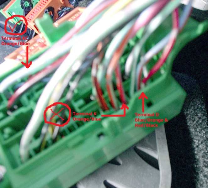
- Locate terminal "AC". It is in the
opposite corner of terminal "D".
Follow the Orange/Blue wire up to where you cut the wire and make note
of it. DO NOT use the terminal "K" Orange/Blue wire.
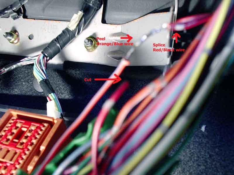
- Swing the Red/Black on the
connector end out of the way and then
strip about 1/2" on the harness side end of it.
- Hold down all the wires in the
harness in the position it would be
when everything is secured. Now place the newly stripped Red/Black wire
next to the terminal "AC"s Orange/Blue wire. Make note of the position.
- Using a pocket knife, peel about
1/2" of insulation on the
terminal "AC"s Orange/Blue wire away. Becareful NOT to cut the wire.
- Twist the newly stripped Red/Black
wire onto the now exposed
Orange/Blue wire then solder them together.
- Tape the now unused connector end
of the Red/Black wire off and
tuck it back into the harness. Tape the newly spliced wires together
also.
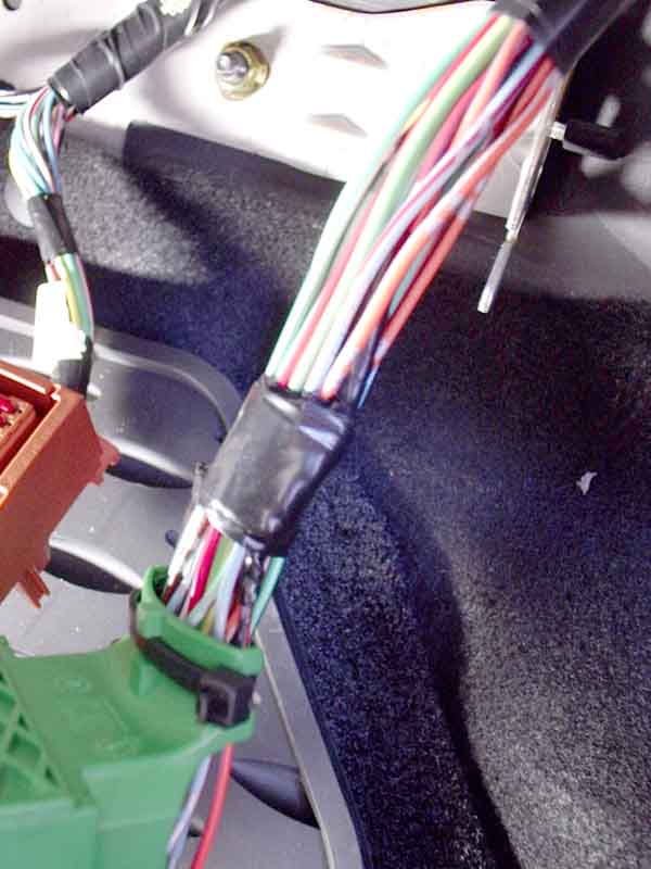
- Install a new zip tie to secure the
wires to the harness connector
the same way the factory did it. "Band" the harness together with tape
in approximately the same location as it was from the factory.
- Locate the small green connector
and unclip its harness from the
bracket. There should be only a few wires on that connector.
- Unwrap the protective loom and
remove the Black/Red wire (connected
to terminal "X") from it.
- Cut the Black/Red wire
approximately 1" from where the protective
loom ended near the connector.
- Tape off the Black/Red wire on the
connector end then tuck it back
into the protective loom.
- Swing the Black/Red wire on the
harness side out of the way. Tape
the protective loom back in its original place.
- Reinstall the clip and harness back
onto the bracket.
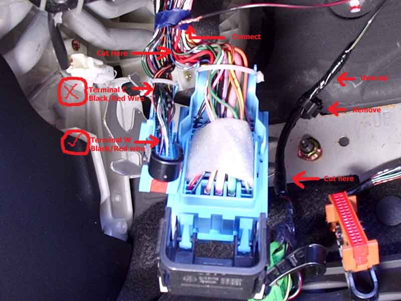
- Locate the Black/Red wire on
terminal "W" on small blue connector.
It is next to the White/Green wire and is nearest the locking lever
when it is in its fully unlocked position. DO NOT use the terminal "C"
Black/Red wire!
- Follow terminal "W"s Black/Red wire
up to about 3/4" from the blue
masking tape a few inches from the connector then cut the wire.
- Swing the Black/Red wire on the
connector end out of the way. Strip
1/2" of the Black/Red wire on harness end.
- Strip 1/2" of the Black/Red wire
that was part of the small
green
connector's harness.
- Cut about 2" of 1/8" heat shrink
tubing and insert it into the
Black/Red wire as far as away as possible from the exposed end.
- Twist the two newly stripped
Black/Red wires together then solder
them.
- Slide the heat shrink tubing down
to the splice point then use a
cigarette lighter to shrink/melt it in place. Ensure your flame is AWAY
from all other objects!
- Tape off the Black/Red wire on the
connector end then tuck it back
into the harness.
- Reconnect the large green connector
to the power junction box then
the two blue connectors. Connectors MUST be seated flush with the
sockets on the power junction box!
- Reinsert the power junction box
into the bracket then flip it back
up and tighten the two screws to resecure the power junction box.
- Reconnect all the other connectors
in the same method as step 30.
- Reonnect the battery and test to
make sure the fog lights work in
ALL light modes on the light controls.
- Reinstall the plastic panel.