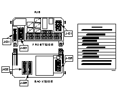
NOTE: Perform steps 4 and 5 for each of the connectors to the PJB (J-01 – J-06), one at a time, before moving onto step 6.

2004 – 2006 MAZDA3
There have been a variety of electrical problems reported where the root cause may be a poorly secured connector, unsecured wire, or bent terminal or pin to the PJB. Many of these problems have occurred after the PJB was removed and reinstalled, as is done for the HVAC diffuser plate or in-cabin filter installation.
Examples of these problems include the following:
While performing diagnostics, there is no communication with the PJB
Door Ajar Light remains on with all of the doors closed
Dome light remains on with doors closed or it is inoperative
Fog Lights are inoperative
A/C not cooling and compressor is inoperative
Power door locks are inoperative
Turn signals or hazards are inoperative
Brake or ABS light remains on with no system problems found
Dimmer switch is inoperative
Keyless entry is inoperative (with ignition key reminder NOT on with key removed from the ignition).
If a vehicle is presenting electrical problems and during diagnosis there are symptoms present that lead you to suspect a poor connection between a wiring harness connector and the PJB, inspect each harness connector and mating terminal on the PJB to determine if they have a proper connection by performing the inspection procedure below.
1. Record all DTC(s) if any are present.
2. Record all pre-set radio stations.
3. Disconnect the negative battery cable.NOTE: Perform steps 4 and 5 for each of the connectors to the PJB (J-01 – J-06), one at a time, before moving onto step 6.
4. Disconnect the connector and inspect for the presence of the following on the connector and mating terminal on the PJB:
Connector: Unsecured or broken wires, bent wire terminals, or corrosion.
Mating Terminal: Bent pins or corrosion.
5. Document the presence of any of the connector or mating terminal problems listed above.
6. Were there any problems found with the connectors or mating terminals?
YES: Go to the next step.
NO: Go to step 8.
7. Make necessary repairs for each of the problems found with the connectors or mating terminals.
8. Reinstall all the connectors to the PJB to their appropriate mating terminals as outlined in Workshop Manual (section 09-40 PASSENGER JUNCTION BOX (PJB) REMOVAL/INSTALLATION).NOTE: When reconnecting each connector to the PJB, pay special attention to correctly seat and connect each connector, listening for CLICK noise made when the connector is properly locked into place.
9. Reconnect the negative battery cable.
10. Check the status of the problems to see if it has been solved.
Solved: Reset customer’s preset radio stations and end repair.
Unsolved: Continue diagnosis, utilizing the Workshop Manual and the Wiring Diagram.