TSB: F013/97
1995 PROTEGE -SUPPLEMENTAL
DIAGNOSTIC PROCEDURES FOR MIL ILLUMINATION DTC'S: P0135, P0400, P0510,
P0703, P1523, P1797
APPLICABLE MODELS
1995 Protege
DESCRIPTION
Attached are supplemental diagnostic procedures, to be used with the
DTC's (Diagnostic Trouble Code) listed below.
NOTE: Not every concern can be
resolved by replacing the PCM (Powertrain Control Module). The
procedures in this supplement have been designed with the latest
information available to help you correctly diagnose the concern the
first time. Service Managers should place supplement in Section F of
the appropriate Workshop Manual .
DIAGNOSTIC PROCEDURE TABLE OF
CONTENTS:
Protege
VICS Solenoid Circuit Malfunction
Models : 95 Protege ES Engine : BP/1.8L (ONLY) Description : VICS
Solenoid Circuit Malfunction (DTC P1523)
Code Definition:
Incorrect voltage signal detected at VICS solenoid circuit terminal
of PCM.
|
Vehicles and PCMs that may set the VICS solenoid circuit
malfunction code during low battery conditions
|
|
Model
|
VIN Range
|
Production Date
|
Affected PCM(s)
|
|
Cal M/T
|
JM1BA142*S0199999
|
Up to 5/11/95
|
BPD5-18-881, A, R, R-0A
|
|
Cal A/T
|
JM1BA142*S0199999
|
Up to 5/11/95
|
BPD6-18-881, A, R, R-0A
|
|
Fed M/T
|
JM1BA142*S0199999
|
Up to 5/11/95
|
BPD3-18-881, A, R, R-0A
|
|
Fed A/T
|
JM1BA142*S0199999
|
Up to 5/11/95
|
BPD4-18-881, A, R, R-0A
|
Diagnostic Chart
|
Step
|
Inspection
|
Action
|
|
1.
|
Retrieve FREEZE FRAME DATA and TROUBLE CODES and record them
on repair order for future use.
|
_
|
Go to next step.
|
|
2.
|
Was FREEZE FRAME DATA stored in memory for P1523 ?
|
Yes
|
Go to next step.
|
|
No
|
Go to step 4.
|
|
3.
|
Did FREEZE FRAME DATA indicate codes were set during a start
up condition ?
Example:
Load 99%, RPM 500, VSS 0 mph etc...
|
Yes
|
Code was most likely caused by a low battery condition during
start up. Inspect battery using S/B 001/97
Category G. If battery checks good, customer should be questioned on
whether the vehicle was stored for a period of time, or if the battery
had gone dead recently.
If vehicle is stored for periods of time or is driven very
little, go to step 6.
|
|
No
|
Go to next step.
|
|
4.
|
Check VICS solenoid circuit.
-
12 volts at the W/R wire (at solenoid connector)
with ignition on and solenoid disconnected.
-
Check terminal tightness of GY/B wire in
connector X-18 (INJ to EM Harness).
-
Continuity between GY/B wire of solenoid
connector and PCM terminal 4K.
-
Check for open between terminals of the solenoid.
Was an open or short found?
|
Yes
|
Make necessary repairs, then go to step 7.
|
|
No
|
Go to next step.
|
|
5.
|
Remove battery and battery tray and check tightness of main
ground cable to transmission bracket.
Was cable found to be loose?
|
Yes
|
Relocate ground cable to bolt that holds bracket to
transmission, then go to step 7.
|
|
No
|
Go to next step.
|
|
6.
|
If
vehicle is driven very little or is stored for periods of time, remove
PCM to confirm that current PCM is "NOT" one of the following:
BPY3-18-881R Fed, M/T BPY4-18-881R Fed, A/T BPY5-18-881R Cal, M/T
BPY6-18-881R Cal, A/T
Is the PCM one of the part numbers listed above?
|
Yes
|
Current PCM has already been modified for this code. Go back
to step 4.
|
|
No
|
Replace PCM, then go to next step.
|
|
7.
|
Clear DTC. Road test vehicle to confirm repair.
Did MIL return ?
|
Yes
|
Go back to step 1.
|
|
No
|
Repairs are complete.
|
NOTE: Check vehicle warranty
history for MIL related repairs. If vehicle has been in for more than
one repair attempt, contact your regional hotline.
EGR Flow Malfunction
Models : 95 Protege Engine : Z5 (ONLY) Description : EGR Flow
Malfunction (DTC P0400)
Code Definition:
The difference between the boost sensor
pressure readings, when the EGR is opened and when it is closed is too
small or too large.
|
Vehicles and PCMs that may set the EGR flow malfunction code,
during certain driving conditions.
|
|
Model
|
VIN Range
|
Production Date
|
Affected PCM(s)
|
|
Fed
|
M/T
|
JM1BA141*S0199999
|
Up to 5/11/95
|
Z501-18-881, A
|
|
A/T
|
JM1BA141*S0199999
|
Up to 5/11/95
|
Z502-18-881, A
|
|
Cal
|
M/T
|
JM1BA141*S0199999
|
Up to 5/11/95
|
Z503-18-881, A
|
|
A/T
|
JM1BA141*S0199999
|
Up to 5/11/95
|
Z504-18-881, A
|
Diagnostic Chart
|
Step
|
Inspection
|
Action
|
|
1.
|
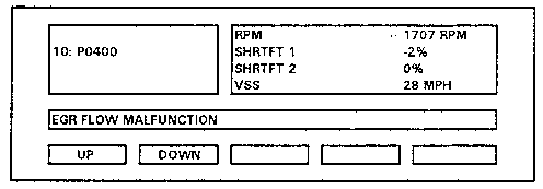
Retrieve FREEZE FRAME DATA and TROUBLE CODES and record them
on repair order for future use.
|
_
|
Go to next step.
|
|
2.
|
Were there any other codes stored in memory ?
|
Yes
|
Perform diagnosis for DTC, then go to next step.
|
|
No
|
Go to next step.
|
|
3.
|
Perform EGR VAC idle simulation test with engine at normal
operating temperature.
Did engine stall out with duty percentage set at 100 % ?
NOTE: During simulation
test, DTC P1402 may be set in memory, it should be ignored, and deleted
when all DTC are erased.
|
Yes
|
Go to next step.
|
|
No
|
Determine
cause of malfunction. Simulation test indicates vacuum is not being
applied to EGR valve. Check for disconnected, pinched or blocked vacuum
hoses, EGR vacuum solenoid or EGR valve, also check for voltage signal
chance at GY/R wire of EGR vacuum solenoid during simulation test.
(Should switch from B+ to below 1.0V during simulation test)
Then go to step 7.
|
|
4.
|
Check
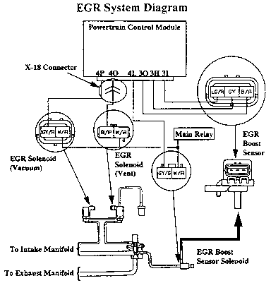
EGR boost sensor solenoid operation. (See workshop manual page F1-35)
Also check EGR boost sensor hose from EGR valve to EGR boost sensor
solenoid for correct routing, pinches, and/or for being disconnected.
(See illustration)
Were there any faults found within the boost sensor solenoid
system ?
|
Yes
|
Make necessary repairs, then go to step 7.
|
|
No
|
Go to next step.
|
|
5.
|
Check EGR boost sensor voltage using the following procedure
and diagrams.
-
With ignition on, measure the voltage between LG/R wire
and the B/R wire, with a voltmeter, from the rear side of the connector.
Specification: 5.0 Vref voltage
-
Disconnect the vacuum hose from the boost sensor.
-
Apply vacuum to the EGR boost sensor using a vacuum pump.
-
Monitor the BARO V voltage with the NGS tester through
the PID
DATA MONITOR AND RECORD screen, or with a voltmeter between the GY wire
and the B/R wire from the rear side of the connector.
Specification:
4.6V @ 0.0 inHg 3.6V @ 5.0 inHg 2.2V @ 13.0 inHg 0.9V @ 20.0 inHg
Were there any faults found with boost sensor?
|
Yes
|
If fault was found in step 1, determine cause of incorrect
Vref voltage.
If fault is found in boost sensor voltage reading, replace
boost sensor, then go to step 7.
|
|
No
|
Go to next step.
|
|

|
|
6.
|
Is the PCM that is currently in the vehicle one of the part
numbers listed below.
Fed. MT: Z5Y1-18-881 AT: Z5Y2-18-881 Cal. MT: Z5Y3-18-881 AT:
Z5Y4-18-881 |
Yes
|
Current PCM has already been modified for code P0400.
Go back to step 3.
|
|
No
|
Replace PCM, then go to next step.
|
|
7.
|
Clear DTC. Road test vehicle to confirm repair.
Did MIL return ?
|
Yes
|
Go back to step 1.
|
|
No
|
Repairs are complete.
|
NOTE: Check vehicle warranty
history for MIL related repairs. If vehicle has been in for more than
one repair attempt, contact your regional hotline.
Neutral /Clutch Switch (MTX),
Transaxle Range Switch (ATX) Circuit Malfunction
Models : 95 Protege Engine : Z5 (1.5L) & BP (1.8L) Description
:Neutral /Clutch Switch (MTX), Transaxle Range Switch (ATX) Circuit
Malfunction. ( DTC P1797 )
Code Definition:
Clutch /Neutral
switch, or Transaxle range switch, (1L) circuit detected no load
(neutral) condition, when PCM judged load (in gear) condition.
Diagnostic Chart
|
Step
|
Inspection
|
Action
|
|
1.
|
Retrieve FREEZE FRAME DATA and TROUBLE CODES and record them
on repair order for future use.
|
_
|
Go to next step.
|
|
2.
|
Were there any codes other then P1797 stored in memory ?
|
Yes
|
Perform diagnosis for DTC, then go to next step.
|
|
No
|
Go to next step.
|
|
3.
|
Monitor the Clutch/Neutral switch Transaxle range switch
neutral/park circuit with the NGS tester.
PID's MTX ( NL SW ) ATX ( TR SW )
Did signals change when transmission was put in and out of
gear and clutch pedal pressed and released ?
|
Yes
|
MTX: Go to next step
ATX: Go to step 5.
|
|
No
|
Check the following
MTX:
-
Clutch & neutral switch ( see page F1-53).
-
For an open or short in B/L wires from terminal 1L of
PCM to
clutch and neutral switches (signal changes from B+ to below 1V when
switches are closed to ground.)
-
For an open in the black wire from the clutch and
neutral switches to ground.
ATX:
-
TRS (Transaxle Range Switch,
(page K-20).
-
For an open or short in the B/L wire terminal 1L of PCM
to the
TRS (signal changes from B+ to below 1V when TRS is in P or N ranges).
-
For open in B/R wire from TRS to ground.
NOTE: See wiring diagrams
for related connectors.
|
|
4.
|
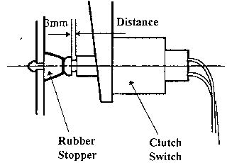
Install updated clutch switch stopper.
Part number: BOY1-43-029
|
|
See installation
instructions.
|
|
5.
|
Check for intermittent open in circuits as mentioned in step 3
for ATX transmission.
Was loose terminal or connector found?
|
Yes
|
Make necessary repair, then go to next step.
|
|
No
|
Go to next step.
|
|
6.
|
Clear DTC, then road test vehicle to confirm MIL does not
return.
Did MIL return ?
|
Yes
|
Go back to step 1.
|
|
No
|
Repair is complete.
|
NOTE: Check vehicle warranty
history for MIL related repairs. If vehicle has been in for more than
one repair attempt, contact your regional hotline.
Clutch Stopper Rubber
Installation Procedure
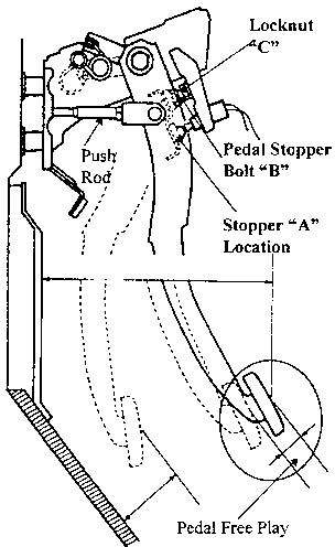
1. Replace the rubber stopper "A" with an improved part.
2. Confirm the distance is (3mm) as shown in Fig. 1 . Fig.
1

3. If less than 3mm, loosen locknut "C", and adjust
distance with pedal stopper bolt "B" as shown in Fig. 2 . Fig. 2

4. After adjustment, tighten locknut "C".
Adjust push rod to eliminate free play to (zero free play).
Closed Throttle Position Switch
Circuit Malfunction
Models : 95 Protege Engine : Z5 ( 1.5L), ATX Description : Closed
Throttle Position Switch Circuit Malfunction (DTC P0510 )
Code Definition:
Terminal 3L of PCM stays 0V or above 1.2V for more than 33.2 seconds
after ignition switch is turned on.
Diagnostic Chart
|
Step
|
Inspection
|
Action
|
|
1.
|
Retrieve FREEZE FRAME DATA and TROUBLE CODES and record them
on repair order for future use.
|
_
|
Go to next step.
|
|
2.
|
Were there any codes other then P0510 stored in memory ?
|
Yes
|
Perform diagnosis for DTC, then go to next step.
|
|
No
|
Customer
should be questioned on what foot they brake with. If customer brakes
with left and depresses the accelerator with the right they should be
informed that this type of driving style sends conflicting signals to
the PCM and will cause codes / MIL. If only DTC P0510 was in memory and
driving style cannot be determined, go to step 3.
|
|
3.
|
Monitor the closed throttle position switch with the NGS
tester.
PID's (CTP SW)
Did signals change when throttle was opened and closed ?
|
Yes
|
Go to next step.
|
|
No
|
Check the following:
-
Closed throttle position switch ( page F1-52).
-
For an open or short in the SB wire from the closed
throttle
position switch to terminal 3L of the PCM (signal changes from below 1V
to B+ when the throttle is opened).
|
|
4.
|
-
Using a digital voltmeter, adjust the TPS to exactly 0.8
volts.
NOTE: Do not exceed
0.8v and don't use the NGS tester readings when doing the above
adjustment.
-
Check BASE IDLE and TIMING, adjust if necessary.
-
Clear DTC
|
_
|
Repair is complete.
|
NOTE: Check vehicle warranty
history for MIL related repairs. If vehicle has been in for more than
one repair attempt, contact your regional hotline.
Front O2 Sensor Heater Circuit
Malfunction
Models : 95 Protege Engine : BP 1.8L (ONLY) Description : Front O2
Sensor Heater Circuit Malfunction (DTC's P0135)
Code Definition:
Incorrect voltage signal detected at front O2 sensor
heater circuit terminal of PCM.
Diagnostic Chart
|
Step
|
Inspection
|
Action
|
|
1.
|
Retrieve FREEZE FRAME DATA and TROUBLE CODES and record them
on repair order for future use.
|
_
|
Go to next step.
|
|
2.
|
Were there any other codes stored in memory ?
|
Yes
|
Perform diagnosis for DTC, then go to next step.
|
|
No
|
Go to step 4.
|
|
3.
|
Did FREEZE FRAME DATA indicate codes were set during a start
up condition ?
Example:
Load 99%, RPM 500, VSS 0 mph etc
|
Yes
|
Code was most likely caused by a low battery condition during,
start up. Inspect battery using S/B
001/97 Category G.
If battery checks good, customer should be questioned on whether the
vehicle was stored for a period of time, or if the battery had gone
dead recently.
If vehicle is stored for periods of time or is driven very
little, go to step 5.
|
|
No
|
Go to next step.
|
|
4.
|
Check front O2 sensor heater circuit for:
-
12 volts at O2 sensor connector B/W
wire (harness side) with ignition on and O2 sensor
disconnected.
-
Continuity between O2 sensor connector
V/Y wire (harness side) and the PCM terminal 3M.
-
The resistance between the white wires of the O2
sensor connector (sensor side) should be approximately 6 at [20C {68F}
].
Was an open or short found?
|
Yes
|
Make necessary repairs, then go to step 6.
|
|
No
|
Go to next step.
|
|
5.
|
Remove battery and battery tray and check tightness of main
ground cable to transmission bracket.
Was cable found to be loose ?
|
Yes
|
Relocate ground cable to bolt that holds bracket to
transmission, then go to step 7.
|
|
No
|
Go to next step.
|
|
6.
|
If
vehicle is driven very little or is stored for periods of time, remove
PCM to confirm that current PCM is NOT one of the following:
BPY3-18-881R Fed, M/T BPY4-18-181R Fed, A/T BPY5-18-881R Cal, M/T
BPY6-18-881R Cal, A/T
Is the PCM one of the part numbers listed above ?
|
Yes
|
Current PCM has already been modified to eliminate this code
from being set under low battery conditions.
Recheck O2 sensor circuit for poor terminal
tightness.
|
|
No
|
Replace PCM, then go to next step.
|
|
7.
|
Clear DTC. Road test vehicle to confirm repair.
Did MIL return ?
|
Yes
|
Go back to step 1.
|
|
No
|
Repairs are complete.
|
NOTE: Check vehicle warranty
history for MIL related repairs. If vehicle has been in for more than
one repair attempt, contact your regional hotline.
Brake Switch Circuit Malfunction
Models : 95 Protege Engine : Z5 1.5 & BP 1.8L, MTX & ATX
Description : Brake Switch Circuit Malfunction (DTC P0703)
Code Definition:
Incorrect voltage signal detected at brake switch circuit terminal
(1Q) of PCM.
Diagnostic Chart
|
Step
|
Inspection
|
Action
|
|
1.
|
Retrieve FREEZE FRAME DATA and TROUBLE CODES and record them
on repair order for future use.
|
_
|
Go to next step.
|
|
2.
|
Are brake lights working ?
|
Yes
|
Go to next step.
|
|
No
|
Go to step 4.
|
|
3.
|
Monitor Brake Switch on NGS tester screen
PID (BRK SW)
Did signal change when brake pedal was pressed and released ?
|
Yes
|
Check
for poor terminal tightness and or loose connectors in the brake switch
circuit that would cause an intermittent open in the G/Y wire between
the brake switch and the PCM terminal 1Q. Then go to step 5.
|
|
No
|
Repair open in the G/Y wire between brake switch and PCM
terminal 1Q. Then go to step 5.
|
|
4.
|
Check for blown 15 amp STOP fuse.
Was fuse blown ?
|
Yes
|
Determine cause of short in brake light circuit, and make
necessary repairs, then go to step 5.
|
|
No
|
Check the following:
-
Check brake light switch.
( See W/S manual page P-7 )
-
Also check for open in G wire between STOP fuse and
brake switch.
Make necessary repairs, then go to step 5.
|
|
5.
|
Clear DTC, road test vehicle to confirm MIL does not return.
Did MIL return ?
|
Yes
|
Go back to step 1.
|
|
No
|
Repair is complete.
|
NOTE: Check vehicle warranty
history for MIL related repairs. If vehicle has been in for more than
one repair attempt, contact your regional hotline.
Freeze Frame Data retrieval
instructions
1. Select "GENERIC OBDII FUNCTIONS" and press "TRIGGER"

2. Press the #8 pad below "CONT"

NOTE: If ALL readiness
tests
have been completed, the next screen will automatically appear.
3. Select "FREEZE FRAME DATA" and press "TRIGGER"

4. Turn the menu dial clockwise or counter clockwise to
monitor desired "PID" By reviewing stored information you can determine
operating conditions when code was set.

If "FREEZE FRAME DATA was not stored in memory the NGS display will
state. "NO TRIGGER CODES SET"


CAUTION: Viewing the NGS
screen
while operating the vehicle is not recommended.
PID Data Monitoring Instructions
1. Select "GENERIC OBDII FUNCTIONS" and press "TRIGGER"

2. Press the #8 pad below "CONT"

NOTE: If ALL readiness
tests
have been completed, the next screen will automatically appear.
3. Select "PID DATA MONITOR" and press "TRIGGER"

4. Turn the menu dial clockwise or counter clockwise to
move highlight bar over desired PIDs and press the trigger to select or
deselect.


Press start to begin displayong your selected PIDs.

CAUTION: Viewing the NGS
screen
while operating the vehicle is not recommended.
Copyright © Mazda North American Operations