TSB: T003/96
KEYLESS ENTRY/SECURITY
INSTALLATION PROCEDURES
APPLICABLE MODELS
1996 Protege with a VIN of JM1BB14**T0328873 and lower.
DESCRIPTION
The wiring
harness for the power door lock relay has changed for the 1996 Protege.
This change affects the installation procedures (Steps 17 and 18)
supplied with the Keyless Entry / Security system for 1996 Protege
models.
USE THIS INFORMATION:
-
ONLY when installing the Keyless Entry/Security system
on 1996 Protege models.
-
To perform Step 17 and Step 18 (Door Lock Connection) instead
of the existing steps (17 and 18 only).
-
If a customer complains of door lock functions after a kit was
installed (i.e. prior to this Service Bulletin).
CAUTION: An intermediate
8-pin
connector was incorporated on early production 1996 Protege Models.
This connector is located approximately 6 inches from the door lock
relay. This connector has been eliminated during the latest production.
THIS CONNECTOR CHANGES THE INSTALLATION METHOD for the "Keyless
Entry/Security" kit. Prior to kit performing the attached new
steps (17 and 18), verify the level of the production unit.
PARTS INFORMATION
|
|
Part Number
|
Description
|
|
0000 88 SECR PR
|
Keyless Entry/Security
|
Keyless Entry/Security
Installation Procedures (Addendum - For Vehicles WITHOUT The 8-Pin
Intermediate Connector)
NOTE: Use these instructions
to replace Steps 17 and 18 ONLY
1. Locate the RED/BLUE wire in the 8-pin connector as shown
below.
-
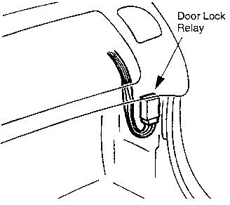
Locate the green door lock relay at the passenger's side
kick panel (just below dash).
Refer to Figure 1
Fig. 1

NOTE: The passenger's
side kick panel was removed in Step 15.
-
Locate the RED/BLUE wire coming down from the 8-pin
door lock relay connector.
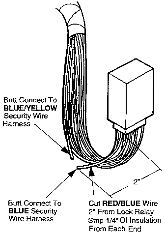
2. Connect the RED/BLUE wire of the 8-pin connector
to the security harness as shown. Refer to Fig. 2
New Step 17.
New Step 18.
-
Butt splice the BLUE security harness wire to the RED/BLUE
wire leading to the door lock relay 8-pin connector.
-
Butt splice the BLUE/YELLOW security harness wire to
the RED/BLUE wire leading AWAY from the door lock relay
8-pin connector. Refer to Fig. 2
NOTE: The power door locks
will not function correctly if this step is not performed as shown.
Fig. 2

RETURN TO KIT INSTALLATION
PROCEDURES
NOTE: The Two (2) stage
unlocking function described in the operator's manual is no longer
possible with this wiring change.
Keyless Entry/Security
Installation Procedures (Addendum - For Vehicles With The 8-Pin
Intermediate Connector)
NOTE: Use these instructions
to replace Step 17 and Step 18 ONLY
1. Locate the BLUE wire in the 8-pin connector as shown
below.
-
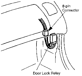
Locate the green door lock relay at the passenger's side
kick panel (just below dash). Refer to Fig. 1
NOTE: The passengers
side kick panel was removed in Step 15.
-
Follow the RED/BLUE wire coming down from the door
lock relay until the 8-pin connector is located (approximately 6" from
the relay).
-
A BLUE wire will be coming from the other end of the
8-pin connector as shown.
Fig. 1

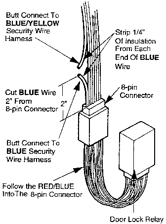
2. Connect the BLUE wire in the 8-pin connector
with the security harness as shown. Refer to Fig. 2
New Step 17.
New Step 18.
-
Butt splice the BLUE security harness wire to the BLUE
wire leading to the 8-pin connector.
-
Butt splice the BLUE/YELLOW security harness wire to
the BLUE wire leading AWAY from the 8-pin connector. Refer to
Fig. 2
NOTE: The power door locks
will not function correctly if this step is not performed as shown.
Fig. 2

RETURN TO KIT INSTALLATION PROCEDURES
Copyright © Mazda North American Operations